Confusing? Yes - it can be - but doesn't have to be! An understanding of the basic principles involved in this concept of "Insulation Resistance" should help to dispel this confusion.
When a capacitor is charged from a DC energy source, an initial high current flows from the energy source into the capacitor. This current flow rapidly decreases toward zero as the capacitor absorbs it. At the same time, the voltage charge on the capacitor starts from zero and rapidly increases toward the energy source voltage value (see Figure 1 ).
Once a steady state charge condition is reached, the current flow into the capacitor should be zero, and the capacitor has a voltage charge equal to the source voltage value. Now, if we had an "ideal" capacitor, no further current would flow in the circuit. Unfortunately, there is no "ideal" capacitor obtainable, and a very small "leakage current" does flow in the circuit. This "leakage current" is a result of electrons physically making their way through the capacitor. In a correctly designed and manufactured unit, the "leakage current" is composed of electrons that make their way through the dielectric itself, around the edges and across the surfaces of the dielectric, and between the leads. Usually, the flow of electrons through the dielectric is far greater than the total of the other paths, and therefore the other paths can be ignored.
This "leakage current" through the dielectric is usually converted to the expression "insulation resistance" by using Ohm's Law.
"Insulation Resistance", then, is a measure of the ability of the dielectric to withstand the passage of electrons through itself and should not be confused with the inherent "series resistance" of the capacitor. For ease of identification, this "insulation resistance" is also referred to as the "parallel" or "shunt" resistance of the capacitor (see Figure 2).


It should be noted here that for comparison purposes, Rs is usually infinitesimal compared to Rp. The magnitude of the leakage current for any capacitor is primarily controlled by the type of dielectric used, the temperature, the capacitance rating, and the time of electrification prior to making the measurement. The thickness of the dielectric and the magnitude of the charging voltage have a comparatively minor effect on the leakage current.
TYPE OF DIELECTRIC
Each dielectric medium has its own inherent insulation resistance characteristic which largely depends on the chemical and molecular structure composition of the material.
TEMPERATURE
Insulation resistance properties of all dielectrics will decrease with increased temperature. This increase in temperature causes an increase in the orbital velocity of the electrons which, in turn, results in a higher flow of electrons through the dielectric.
CAPACITANCE RATING
Inasmuch as the capacitance rating in effect reflects the total area (square inches) of dielectric in the capacitor, it can (within design limits) be used as a direct measure for insulation resistance. In general, if we double the area of dielectric, we also double the number of paths for electrons to flow through the dielectric, and the final result is double the leakage current (one-half the insulation resistance).
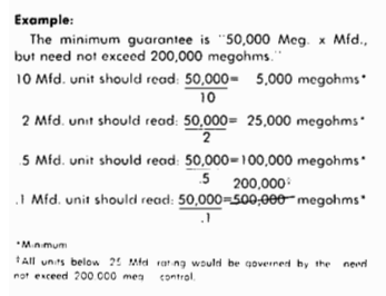
Now, however, this inverse ratio between the capacitance and insulation resistance for any given dielectric provides the capacitor manufacturer with a handy tool for designating a single value of insulation resistance as a guarantee to cover all capacitance values for that line. This is done by multiplying the insulation resistance (ohms) times the capacitance (farads) to arrive at a constant value of (ohms x farads) or, more commonly (megohms x microfarads).
This use of a limiting value became necessary as a convenience when plastic films made their appearance as capacitor dielectrics. These plastic films have such high inherent insulation resistance that very small values of capacitance ratings would require instruments that could measure in the millions of megohms area. Since present standard measuring equipment is not capable of reasonable accuracy above approximately 500,000 megohms, this limitation is used.
Note: It is "megohms times microfarad" not "megohms per microfarad."
TIME OF ELECTRIFICATION
If we were to designate any single factor in this discussion of insulation resistance that is the most neglected and subject to the highest error probability, "time of electrification" would certainly haven to be considered. What must be recognized here is the fact that all dielectrics have some degree of chemical polarity, and therefore are subject to "interfacial polarization." A highly polar dielectric (such as mylar) would have a high degree of "interfacial polarization" which, as we measure it would manifest itself as a fairly high value of "dielectric absorption." On the other hand, a non-polar dielectric (such as polystyrene) would show its low degree of "interfacial polarization" as a low value of dielectric absorption.
How long it takes to reach this steady state condition will vary not only with the dielectric, but also with many other factors. However, all units will allow the general pattern shown in Figure 3. For illustration purposes only, the curves approximate the typical curves for non-impregnated mylar dielectric capacitors. The effect of temperature on both the insulation resistance value itself and the time to reach a steady state condition is shown. The variance of the insulation resistance value between "identical" units from the same lot is also depicted by the dotted lines on the +25°C (only) curve.
The "time of electrification" should always be noted when specifying insulation resistance value whether it be a user's specification or a manufacturer's catalog sheet involved. Two minutes electrification time is most common and in general usage. Figure 4 shows a comparative analysis of the typical curves of insulation resistance vs. temperature for various dielectrics (two minute electrification time). What must be kept in mind when analyzing Figure 4 is that curves are average figures only and it is entirely possible to get individual capacitance that will vary as much as 1 O or 20 to 1 from the average value.
The effect of the insulation resistance value, both in magnitude and how it varies with time and temperature, is quite critical in circuitry where leakage of current through the capacitor can cause malfunction or undesirable results to occur. Prime examples of this type of application can occur in most coupling or decoupling circuits, and some blocking, timing, or signal pickup situations.

