Limited supply. Consult factory.
This metallized polycarbonate capacitor series exhibits superior electrical characteristics over an extremely wide temperature range. Their miniature size, high Q, excellent IR and capacitance stability make them ideally suited to filter network and other low-loss high frequency applications.
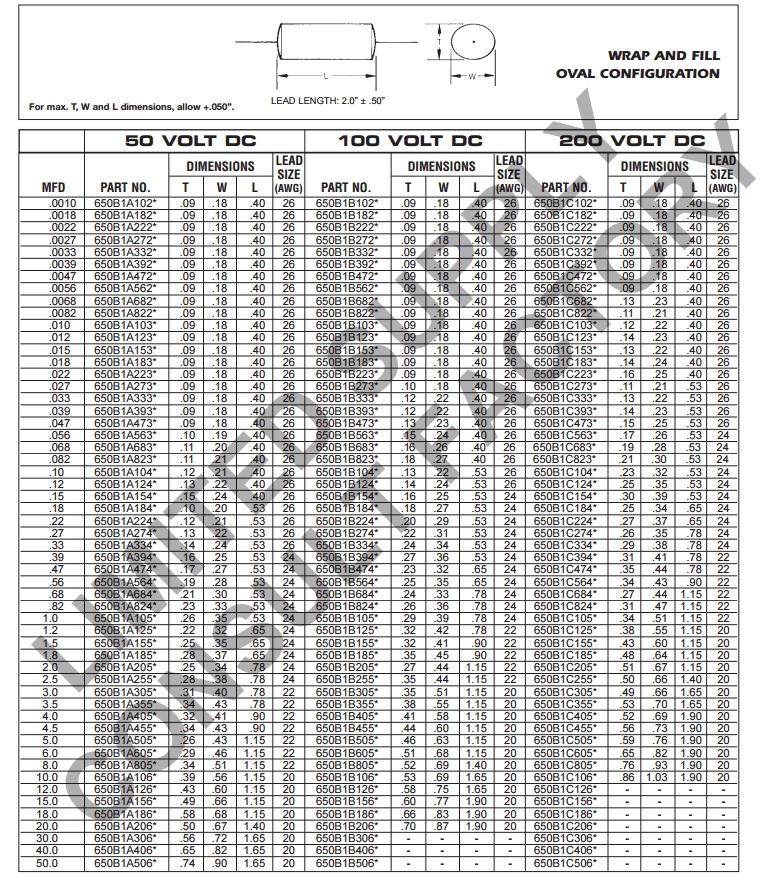
A wide variety of sizes and configurations are available: axial-lead wrap and fill (in oval and round shapes) and rectangular epoxy case (axial and radial leads).
All capacitors feature extended foil construction and standard tin-coated copper-clad steel leads. Nickel, copper, dumet and other special leads are available.
Protective clear wrap is offered on all wrap and fill units. Please add .010” to maximum T and W dimension for protective clear wrap.
The potting material and endfills of Electrocube’s capacitors meet or exceed the flammability requirements of UL94VO.
Dimensional variations for all MFD values are available with the same volume to meet your design requirements.
| Temperature: | -55°C to +125°C. |
| Dielectric Strength: | Will withstand 200% at rated voltage and 25°C for a period not to exceed 1 minute; current limited to 5 mA. |
| Life Test: | Will withstand 140% rated voltage for 250 hours at +125°C, with not more than 1 failure in 12 permitted. |
| Dissipation Factor: | Shall not exceed 0.3% at 25°C. |
| Dielectric Absorption: | Shall not exceed 0.2% at 25°C per MIL-C-19978. |
| Acceptance Criteria: | Measurement frequency for capacitance and dissipation factor shall be 1000 Hz for values to 1 mfd; 120 Hz for values of 1 mfd and over. |
| Insulation Resistance: | At rated voltage or 500V, whichever is less, units shall meet the minimum values below: |


NOTES:
The following capacitor series (625B, 625C, 625D) are not recommended for new design. For technical data or alternate design and application information, consult factory.
For information regarding insulating sleeves, mountings, special terminals, non-standard leads, circuit connections and other hardware, please consult factory.
For styles and ratings not shown, or for unusual requirements necessitated by special circuit applications (including higher IR or lower DF), consult the factory direct.
All Electrocube film capacitors have endfills and tape that meet or exceed the flammability requirements of UL94V0.