"WARNING! - Do not remove wire from capacitor terminals until ready for use."
"Caution! - Removal of wire joining capacitor terminals except immediately prior to use or testing may result in severe electrical shock."
In spite of the above admonitions, usually in the form of tags affixed to most high voltage/high energy capacitors, many technicians, servicemen, and assembly workers are still electrically "shocked" each year; in some cases, severely enough to require hospitalization.
In one case, a manufacturer received a very bitter letter from one victim who threatened to sue for "gross negligence" in shipping a "charged" capacitor. And, if you'll pardon the unintentional pun - a very serious "charge" indeed!
Of course, no manufacturer of capacitors will deliberately ship a charged capacitor to a customer. On the contrary, very elaborate precautions are in effect to avoid this very circumstance from happening.
But - you might well question - if the manufacturer didn't "goof" and ship a "charged" capacitor - how come these people are getting shocked by so-called uncharged capacitors?
What we are seeing here is an extreme example of the result of a phenomenon found in all capacitors. This phenomenon has been given many names, such as, "dielectric soak", "voltage retention", "residual charge", "electric absorption", etc. In this article, we will refer to this phenomenon as "dielectric absorption", a term that has gained general acceptance in the industry.
First, let us demonstrate what this phenomenon is and how we observe and measure it.
Initial condition: All switches open.
We now divide the recovery voltage (Er) by the charging voltage (Eo), convert to a percent figure by multiplying by 100, and our result is a "percent dielectric absorption" (%DA) figure.
In basic terms then, we may now state that the phenomenon of dielectric absorption occurs because a capacitor, once charged, will not give up all this stored energy under transient discharge conditions. The "%DA" figure is a relative measurement of this reluctance to discharge completely.
 >
>
In addition, the magnitude of this %DA figure will vary considerably for different materials and their impregnants.
Let us now examine the mechanics involved in this charge-discharge-recovery voltage cycle for a capacitor. This will help us understand why this phenomenon occurs and the general effect exerted by each controlling factor. Referring to Figure 1 and the step sequence for the demonstration:
The closing of the charging switch initiates the process of charging the capacitor to an ultimate voltage potential equal to the voltage source E0. During this time it takes to charge the capacitor, electrons will, in effect, move from the voltage source to the capacitor. In the capacitor, the initial electrons move out into the dielectric and electrically orient the dielectric molecules into their proper positive and negative directional relationship. As long as the switch (Sc) remains closed, these initial electrons (or replacements for them) must remain in the dielectric and maintain this electrical polarization of the dielectric molecules. As such, they are referred to as "bound" electrons.
Immediately following these initial electrons, other electrons saturate the electrode plate and the dielectric. The electrons that are also in the dielectric but not "bound" are referred to as "free" electrons. It is some of these "free" electrons that eventually make their way across the dielectric to the other electrode that constitutes what is known as the "leakage current" of the capacitor.
At this point, it is quite apparent that the magnitude of the charging voltage has a direct, exponential control on the total amount of electrons stored in the capacitor. The charging time has a direct (but not linear) control on the total electrons saturating the dielectric.
This removes the charging source Eo. It is interesting to note that if the capacitor were allowed to remain in this condition for an appreciable length of time, it would gradually lose its charge. The time element for this to happen would be primarily controlled by the dielectric material itself.
The discharge cycle has now been initiated. The electrons stored on the electrode would immediately "flow" through the discharge circuit (on its way to the other capacitor electrode). These would be followed in time sequence by the tree electrons that are in the dielectric as they make their way back to the proper electrode. Finally, as the voltage gradient between the capacitor electrodes reduces to zero the "bound" electrons are released to follow the "free" electrons.
The effect of the discharge time is quite apparent here, the longer the time, the more complete will be the reduction of electrons left in the capacitor dielectric.
This removes the discharge circuit. At this sequence point, the remaining "free" electrons in the dialectic and the "bound" electrons will, with time, make their way to the proper electrode. They will now establish a potential gradient between the capacitor electrodes.
This inserts the voltmeter into the capacitor circuit and a reading of the "recovery voltage" can be made.
Here. the time after discharge that a reading is made of the "recovery voltage" obviously affects the magnitude of that voltage reading since this "recovery voltage" is itself a function of time.
The effect that temperature has on this dielectric absorption cycle is primarily one of time distortion. An increase in temperature will in general speed up all time cycles concerned. Thus, if temperature were the only variable in a series of measurements on the same dielectric unit, the %DA figure for the highest temperature would be the highest in magnitude.
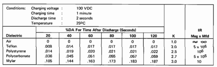
Figure 2 shows not only the comparative values of the %DA figure for some typical dielectrics, but also illustrates the effect of the time of measurement.
If we now reflect for a moment and note the final two columns in Figure 2 where the respective dielectric constants (K) and insulation resistance (IR) properties of the dielectric have been tabulated on a comparative basis, we note the obvious pattern that the lower dielectric constant materials have the better insulation resistance and %DA characteristics.
The addition of an impregnating or filling material to any of the above dielectrics will immediately cause the units to assume the %DA figure associated with that material. In most cases, the common oils used for impregnation will exhibit a %DA figure of approximately 2.0 under the typical measurement conditions of our examples.
If the dielectric absorption is a critical factor in an electrical circuit, such as those circuits that depend on a specific time delay or speed of response for accurate functioning, then a design engineer must recognize the need for an analysis of this factor in his selection of capacitors.
Those design engineers who must also deal in high voltage and/or high energy capacitors must also be cognizant of the safety hazards involved. For example, an energy storage capacitor rated at 20,000 volts, paper-oil dielectric can easily recover to several hundred volts after initial discharge. It is for this reason that these types of units are shipped by the manufacturer with a permanent wire connecting the terminals serving as a permanent discharge curcuit and thus avoiding the build-up of a recovery voltage.
Too often overlooked is the fact that once this wire and tag have been removed by incoming inspection or engineering personnel for the purpose of testing these units, they should be replaced and kept in place until the units are put into service. Unlike the reaction to a similar admonition that is used on a very different product and in effect says "usage may be hazardous to your health", in the case of these capacitor warnings - you'd better believe it!
 >
>