Paper and plastic film capacitors are subject to two classic failure modes: opens or shorts. Included in these categories are intermittent opens, shorts or high resistance shorts. In addition to these failures, capacitors may fail due to capacitance drift, instability with temperature, high dissipation factor or low insulation resistance.
Failures can be the result of electrical, mechanical, or environmental overstress, "wear-out" due to dielectric degradation during operation, or manufacturing defects.
The classic capacitor failure mechanism is dielectric breakdown. The dielectric in the capacitor is subjected to the full potential to which the device is charged and, due to small capacitor physical sizes, high electrical stresses are common. Dielectric breakdowns may develop after many hours of satisfactory operation. There are numerous causes which could be associated with operational failures. If the device is operating at or below its maximum rated conditions, most dielectric materials gradually deteriorate with time and temperature to the point of eventual failure. Most of the common dielectric materials undergo a slow aging process by which they become brittle and are more susceptible to cracking. The higher the temperature, the more the process is accelerated. Chemical or aqueous cleaning may also have an adverse effect on capacitors (See Technical Bulletin #11 ).
Dielectric breakdown may occur as a result of misapplication or high voltage transients (surges). The capacitor may survive many repeated applications of high voltage transients; however, this may cause a premature failure.
Open capacitors usually occur as a result of overstress in an application. For instance, operation of DC rated capacitors at high AC current levels can cause a localized heating at the end terminations. The localized heating is caused by high 12R losses. (See Technical Bulletin #10). Continued operation of the capacitor can result in increased end termination resistance, additional heating, and eventual failure. The "open" condition is caused by a separation of the end-connection of the capacitor. This condition occurs more often with capacitors of low capacitance and a diameter of less than .25 inch. This is why care must be taken when selecting a capacitor for AC applications.
Mounting capacitors by the leads in a high vibration environment may also cause an "open" condition. Military specifications require that components weighing more than one-half ounce cannot be mounted only by their leads. The lead wire may fatigue and break at the egress area if a severe resonance is reached. The capacitor body must be fastened into place by use of a clamp or a structural adhesive.
The following list is a summary of the most common environmentally "critical factors" with respect to capacitors. The design engineer must take into consideration his own applications and the effects caused by combinations of various environmental factors.
The service life of a capacitor must be taken into consideration. The service life decreases as the temperature increases.
Capacitance will vary up and down with temperature depending upon the dielectric. This is caused by a change in the dielectric constant and an expansion or shrinking of the dielectric material/electrodes itself. Changes in capacitance can be the result of excessive clamping pressures on non-rigid enclosures. (See Technical Bulletin #4).
As the temperature of a capacitor is increased the insulation resistance decreases. This is due to increased electron activity. Low insulation resistance can also be the result of moisture trapped in the windings, a result of prolonged exposure to excessive humidity, or moisture trapped during the manufacturing process. (See Technical Bulletin #5).
The dissipation factor is a complex function involved with the "inefficiency" of the capacitor. The "D.F." may vary either up or down with increased temperature depending upon the dielectric material. (See Technical Bulletin #6).
The dielectric strength (dielectric withstanding voltage or "stress" voltage) level decreases as the temperature increases. This is due to the chemical activity of the dielectric material which causes a change in the physical or electrical properties of the capacitor.
Hermetically Sealed Capacitors
As the temperature increases the internal pressure inside the capacitor increases. If the internal pressure becomes great enough, it can cause a breach in the capacitor, which can then cause leakage of impregnation fluid or moisture susceptibility.
Epoxy Encased/Wrap and Fill Capacitors
The epoxy seals on both epoxy encased and wrap and fill capacitors will withstand short-term exposure to high humidity environments without degradation. Epoxies and "plastic" tapes will form a "pseudo-impervious-barrier" to water and chemicals. These case materials are somewhat porous and through osmosis can cause contaminants to enter the capacitor. The second area of contaminate absorption is the leadwire/epoxy interface. Since epoxies cannot 100% bond to tinned lead wires, there can be a path formed, up the lead wire, into the capacitor section. This can be aggravated by aqueous cleaning of circuit boards. (Electrocube offers a solution to moisture/ contaminant absorption. See Technical Bulletin #11).
A capacitor can be mechanically destroyed or may malfunction if it is not designed, manufactured, or installed to meet the vibration, shock or acceleration requirement within a particular application. Movement of the capacitor within the case can cause low I.R., shorts or opens. Fatigue in the leads or mounting brackets can also cause a catastrophic failure.
The altitude at which hermetically sealed capacitors are to be operated will control the voltage rating of the capacitor. As the barometric pressure decreases so does the terminal "arc-over" susceptibility increase.
Non-hermetic capacitors can be affected by internal stresses due to pressure changes. This can be in the form of capacitance changes or dielectric arc-overs as well as low I.R.
Heat transfer can be also affected by high altitude operation. Heat generated at the lead terminations cannot be dissipated properly and can result in high 12R losses and eventual failure.
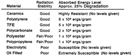
For space and nuclear applications, radiation capabilities of capacitors must be taken into consideration. Electrical degradation in the form of dielectric embrittlement can take place causing "shorts" or "opens" to occur. Radiation effects in capacitors may be either transient or permanent. Transient effects are changes in the electrical parameters, which are changes in capacitance and decreases in insulation resistance (only during irradiation). Special techniques and processes can be applied to capacitors to improve the radiation resistances for various plastic dielectrics.
Capacitors with inorganic dielectrics and cases, such as glass, are more radiation resistant than those utilizing organic materials such as oil-impregnated paper. In addition to electrical changes induced by ionizing radiation and particle bombardment, gas evolution from impregnants may build disruptive pressures in hermetically sealed cases.
Figure 1 lists the various categories of capacitors in descending order of their radiation resistance (most resistant style listed first) Per Space Material Handbook NASA SP-3025:
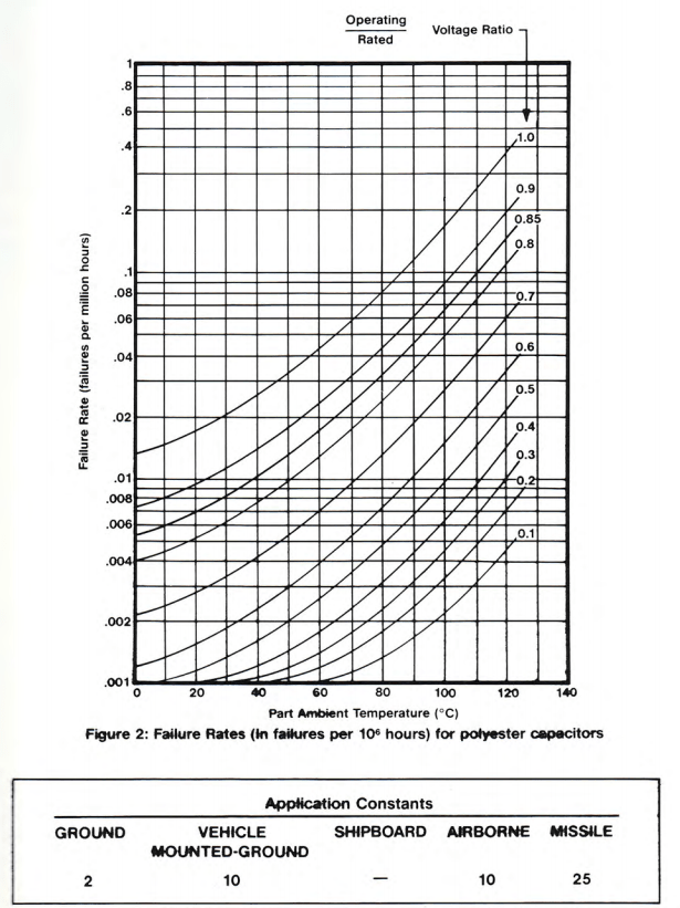
Figures 2 and 3 are taken from Mil-HBK-217. The rates are representative of Polyester capacitors type CTM (capacitors in nonmetallic cases). The data should be used as reference only and can be applied to most nonQPL plastic capacitors. The failure rates are for general rates to be expected. For OPL products Mil-HBK-217 should be consulted for a particular application.